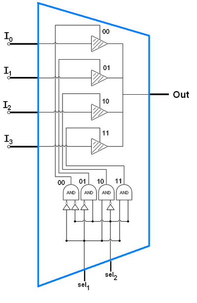
10+ mux block diagram
For more information about specific device features consult 2. In a previous post in this series we looked at the way we use the VHDL entity architecture and library keywords.

Multiplexer Wikiwand
Block Diagram 3 Features 4 Applications 5 1 Family Member Comparison 10 11 Family Nomenclature 10 12 Comparison 10 2 Pin Definitions 11 21 Pin Layout 11.

. The 116 Demux consists of 1 data input bit 4 control bits and 16 output bits. Click to see the answer Q. The microprocessor unit MPU subsystem is based on the ARM Cortex-A8 processor and the PowerVR SGX Graphics Accelerator subsystem provides 3D graphics acceleration to support display and gaming effects.
Multifunction pins such as db15os2 are. Function Block Diagram is easy to learn and provides a lot of possibilities. 10 to 1 Mux with 4 to 1 Mux.
The contains the subsystems shown in the Functional Block Diagram and a brief description of each follows. Start defining each gate within a module. Feb 10 2010 Messages 26 Helped 0 Reputation 0 Reaction score 0 Trophy points 1281 Location bangalore.
The block diagram of 1x16 De-Multiplexer using lower order Multiplexers is shown in the following figure. FUSB307B Block Diagram SCALE 31 WQFN16 3 x 3 05P CASE 510BS ORDERING INFORMATION 8 DBG_N GND 4 ORIENT 3 CC2 2 VCONN 1 CC1 9 GPIO2 10 INT_N 11 SCL1 12 SDA1 7 VDD 6 VBUS 5 LDO 13 SRC 14 SNK 15 GND 16 GPIO1. 2Click on the part number above to see a block diagram for each corresponding part number.
The Cyclone V SoC internal block diagram Image Source. Nected to AGND at the input terminal block and 32000 samples are acquired at the maximum rate available at each setting. Si5330x Ordering Guide Part Number Package Pb-Free ROHS-6 Temperature.
GPIO Matrix 43 Revision History 48 Espressif Systems 7 Submit Documentation Feedback ESP32-S2 Family Datasheet V13. This is a diagram of the action or the successive approximation ADC using Vref as 5V. The two electrostatic deflection plates deflect the accelerated beam by the application of voltage.
The diagram given below shows the internal structure of the CRT. A block diagram of the EFM32PG22 family is shown in Figure 31 Detailed EFM32PG22 Block Diagram on page 8. IO MUX 42 A2.
With 21 input mux Yes 2 10 Diff 20 SE Yes No Individual Yes No Si53306-B-GM 4 output universal buffer single input. 4 bit ADC Operation. I 0 I 1 I 2 I 3 I 4 I 5 I 6 I 7 I 8 I 9 I 10 I 11 I 12 I 13 I 14.
13591-001 1mΩ r fb 1mΩ r fb first-order lpf 1mΩ r fb 1mΩ r fb first-order lpf v0a v0agnd 1mΩ r fb 1mΩ r fb v7a v7agnd v0b v0bgnd v7b v7bgnd 91 mux busy convst control inputs clk osc refinout refsel serpar ser1w osr digital filter 25v ref refcap notes 1. Functional block diagram. The diagram shows a superset of features available on the family which vary by OPN.
Add DMA block diagram. The dma_if_mux module enables sharing the DMA interface across several DMA clients. Jan 21 2014.
Measurement Computing 3508 946-5100. Decide which logical gates you want to implement the circuit with. Cornell University At the other end of the scale the Stratix 10 SX targets high-performance applications in communications data center acceleration high-performance computing HPC radar processing and ASIC prototyping.
Mux selection and Debug Accessory the TCPM writes to STD_OUT_CFG. The outputs of upper 1x8 De-Multiplexer are Y 15 to Y 8 and the. Heres the module for AND gate with the module name and_gate.
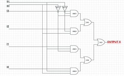
In the 81 MUX we need eight AND gates one OR gate and three NOT gates. 2-a- design a 8XJ MUX using 4X1 MUX and 2X1 MUX. A sharply focused beam is produced by the electron gun assembly.
This module handles the tags and select lines appropriately on both the descriptor and segmented memory interface for plug-and-play operation without address assignment - routing is completely determined by. This high-velocity beam strikes the fluorescent screen thus causing a luminous spot on the screen. Analog Peripherals Clock Management HFRCO Core and Memory Up to 512.
The port-list will. Logic diagram for 81 MUX Verilog code for 81 mux using structural modeling. Functional block diagram 16 16 16 dutgnd measvh03 guard03 cgalm sdo sclksdi sync cpol0 sclk cpol2 cpo0 cpoh2 cpo1 cpol3 cpo2 cpoh3 cpo3 serial interface cpoh0 sdi cpol1 sync cpoh1 sdo.
As one of the official PLC programming languages described in IEC 61131-3 FBD is fundamental for all PLC programmers. Here a 4 bit ADC is shown but the principle is the same however many bits are used. Mux measvh3 foh3 extmeasih3 extmeasil3 ch1 ch0 ch2 ch3 foh2 extfoh2 extmeasih2 extmeasil2 measvh2 guard2 measvh1 extmeasil1 foh1 extfoh1 cff1.
I want a block diagram for hamming code like in terms of addersmuxdemux. 73 Si5332 5x5 mm 32-QFN Package Diagram External Crystal Versions 匀椀㔀䄀䈀䌀䐀尩 54 74 Si5332 6x6 mm 48-LGA Package Diagram Embedded Crystal Versions 匀椀㔀䔀䘀䜀䠀䰀尩. In this post we discuss the VHDL logical operators when-else statements with-select statements and instantiationThese basic techniques allow us to model simple digital circuits.
8 Data Bus Microcontroller with High-Speed USB 20. Initially the input voltage Vin is greater than the starting value of the DAC voltage set by initial DAC value of B1000 so this bit is kept. Find the transfer function of the following figures using block diagram reduction and Mansion A.
With this extension however you can bypass that annoying popup and keep not signed in twitter-surfingUpdatev200 - 2022-07-26. That FPGA includes a quad-core 64-bit Arm Cortex-A53. These are important concepts which provide structure to our.
4 a Block Diagram of 18 Demux b Circuit Diagram of 18 Demux using Logic Gates. The common selection lines s 2 s 1 s 0 are applied to both 1x8 De-Multiplexers. Fig 4 illustrates the block diagram and circuit diagram of 18 Demux.
It is a great way to implement everything from logic to timers PID controllers and even a SCADA system in your solution etc. USB-1608G Series Block Diagram.

Building A Custom Test Multiplexer With No Engineering Required Pulse Research Lab
What Is A Barrel Shifter Quora

Scaling Capacity Of Fiber Optic Transmission Systems Via Silicon Photonics

Implementing A Two Axis Robot Arm Controller Without An Mcu Edn Asia
Multiplexer Wikiwand
Encoder Digital Wikiwand

Pin On Food Recipes

Multiplexer Wikiwand
Multiplexer Wikiwand
Sparkfun Analog Digital Mux Breakout Cd74hc4067 Bob 09056 Sparkfun Electronics

Building A Custom Test Multiplexer With No Engineering Required Pulse Research Lab

Analog Devices Cn0262 Block Diagram Mems Microphone Analog Devices Circuit Diagram

Multiplexer Logisim 16 Bit Bits Block Diagram
2
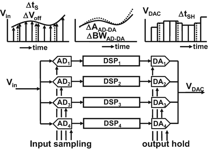
Time Interleaving Springerlink

Block Diagram Of The Receiver Section All High Speed Signal Download Scientific Diagram

Block Diagram Of The Receiver Section All High Speed Signal Download Scientific Diagram